After spending some time researching methods for rendering voxel isosurfaces, I decided to implement a dual contouring algorithm – which is the “dual” case of the infamous marching cubes algorithm. It’s still far from finished but it’s produced some promising results so far…
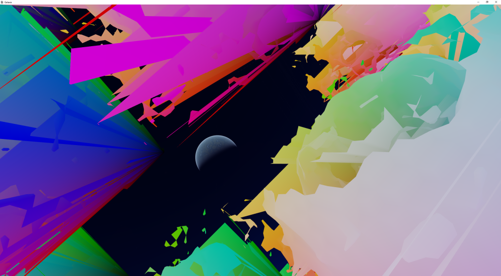
 [Fuzzy blobs: spheres with added ridged noise. Header image: spheres with negative ridged noise. And a planet.]
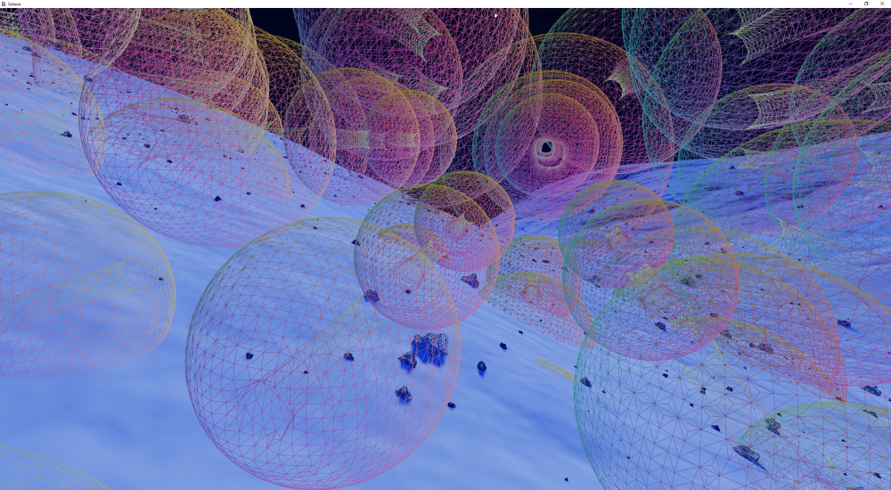
Comparing the filled and the wireframe views of the image below can help reveal how the dual contouring is done. For each voxel “cell” (a cube with a voxel point at each corner) in the grid, between 0 and 3 quads can be generated, depending on which of the corner points are above/below a threshold value. If all corners are on the same side of the threshold, no quads are output.
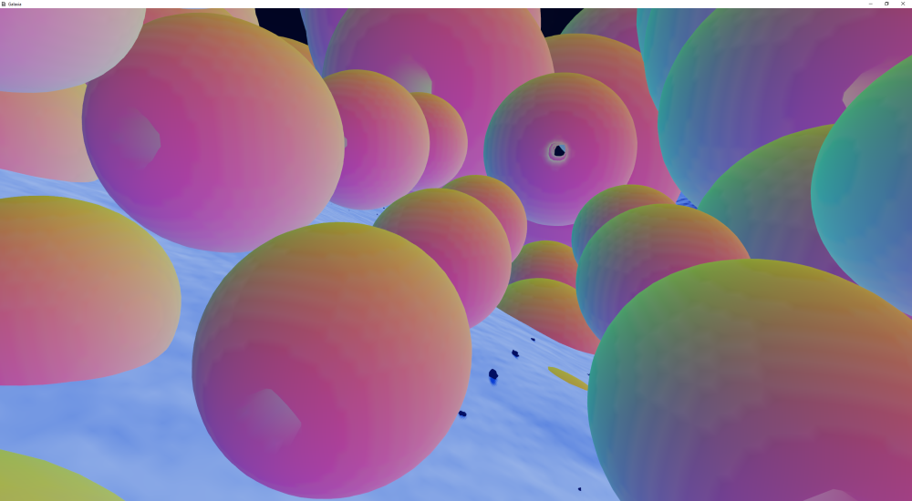
The output vertex points also need to be moved to an estimate of where the surface would be, based on the voxel gradients along each cell edge. This results in the perfectly round spheres above. Probably the easiest way to visualise what is happening is to think of the terrain in Minecraft. Basically we start out with all those orthogonal cubic faces and then “flatten” the vertices into the smooth surface. If this last step weren’t done, the output would actually look just like Minecraft.
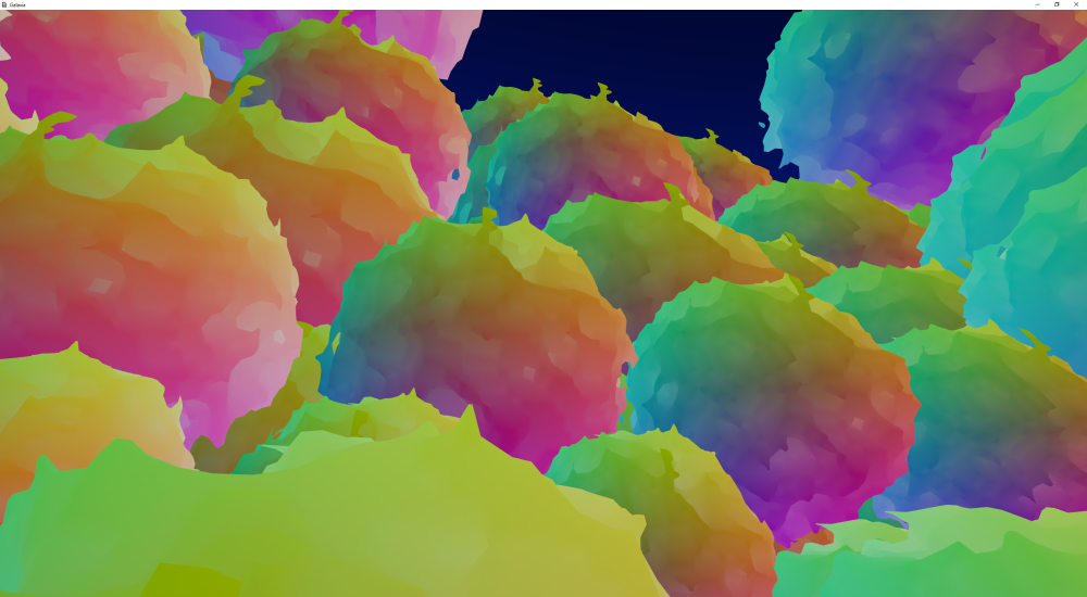
Note that the colours used here are the vertex coordinates in the grid, so some “blockiness” is visible in the colours due to them not being offset in the same manner as the vertex positions.
To get it running at an interactive rate, I’ve devised a method of generating up to 128 voxel “chunks” (each 32x32x32 voxels) at a time all on the GPU. The results of of the chunk generation are put into larger vertex and index buffer caches, holding 256+ chunks (depending on available graphics memory). The updating is currently done immediately before rendering. I’m hesitant to introduce a chunk streaming approach due to the potential few frames that there would be nothing to display – so I’ve sacrificed some “fluidity” here, meaning that as the camera moves/rotates and uncached chunks need to be generated, they are done in that frame, there and then, potentially causing the frame to take much longer to render. Currently my terrain system does the same thing, in order to be able to ensure bits of the terrain don’t suddenly blink out of existence before a higher or lower LOD is generated. But it’s not actually causing a noticeable frame drop yet. In particular if the camera’s velocity is kept small, generally only a small number of chunks need to be updated each frame, which is quite fast, and the cache saves having to regenerate everything if the camera is just rotated in circles.
An outline of the chunk update process is as follows: (CS: compute shader; GS: geometry shader – both using Shader Model 4.0)
- (CS) Fill a 35x35x35 uint grid of the data, with 16 bits each of isovalue and material data. Currently I’m just using static functions but eventually I want to have it generate a surface based off my terrain’s heightmaps.
- (CS) “March” the voxel cells and determine the “case index”. I used a method based off this paper (see p46). The output data is well bitsmashed, with 4 voxel cells in each uint value that the compute shader outputs. Also in there is packed a value for each cell for whether the vertex is required to generate the surface, and the quad count for the cell.
- (CS) “Reduce” the vertex and quad counts along the Z axis, so for each chunk a 32×32 grid of values are output, each “pixel” containing the sum of vertex and index counts along each row of voxels.
- (CS) Perform the same again, except collapsing the 32×32 grid into a 1×32 row of sums.
- (CS) Perform the same yet again, to finally end up with 1 value for each chunk containing the number of vertices and quads for each chunk. (16 bits each).
- (CS) Perform the reverse procedure as the above, but outputting the vertex and quad offsets for each row into a 1×32 row of uints.
- (CS) Continue the “re-expansion” step to get a 32×32 grid of offsets.
- (CS) Final re-expansion step, resulting in a 32x32x32 grid of vertex indices and quad offsets.
- (CS) Update the cached “counts” buffer, which contains how many vertices and quads are to be rendered for each cached chunk.
- (CS) Update the cached vertices buffer. The CS is run for each cell in each updated chunk. If an index is available for output, the vertex position is generated using the “contouring” part of the dual contouring algorithm. The vertex must always remain within its cell, and is found simply by linearly interpolating all the cell’s estimated edge intersection points. The index found in the reduction/re-expansion phase is used here to perform a scatter write of the vertex data.
- (CS) Update the cached indices buffer. A similar thing is done here as for the vertex buffer above, except for the quads in each cell. The only difference here is that each cell could output up to 3 quads, as opposed to the single vertex above. But that’s OK, because the “quad index” generated previously will have accounted for that.
- (GS) At this stage, all the data required for rendering has been prepared. To render the quads, a geometry shader is run with 8192 input primitives. The vertex ID is simply passed from the vertex shader to the GS, and the GS runs using points as input. If the vertex ID arriving in the GS is higher than the number of vertices in the chunk (read from the “cached counts” buffer), nothing is output. Otherwise, between 1 and 3 quads can be output here. The vertex and index data generated in the previous steps are used here to determine the vertices and quads to be output.
Unfortunately this method is slightly wasteful in that potentially many GS invocations are not outputting anything, and the total number of quads for each chunk does have a limit (albeit an arbitrary one designed to reduce this GS wastefulness). But with the shader exiting without doing unnecessary calculations, this impact can be almost unnoticeable on a modern GPU, considering they are designed to run many millions of invocations of shader programs in each frame. Using this technique also allows for no communication back from the GPU to the CPU, namely the number of quads required to draw each cell. This is important because it avoids stalling the pipeline. If Shader Model 5.0 is used, this issue can be removed completely by use of the DrawInstancedIndirect() function, although even that still leaves a little to be desired (a draw call would be required for each chunk). With the current method, only a single draw call is needed to draw all the chunks.
There is plenty more to say on this subject, but honestly this is too long already and probably no-one will read it anyway – but congrats if you got here! :D. Obviously still on the to-do list is to have different data in each chunk (terrain data, asteroid data, etc), and LODs, which will likely be quite fiddly, especially the LOD fading.
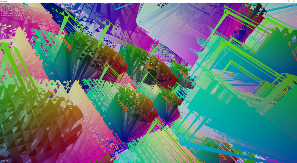
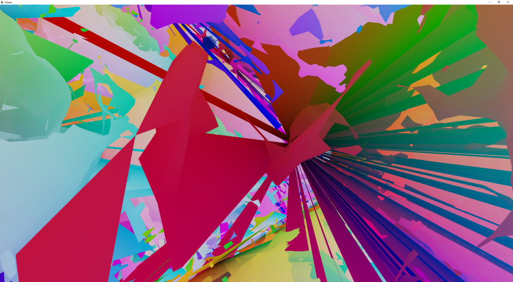
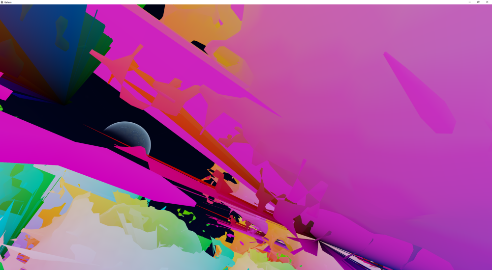
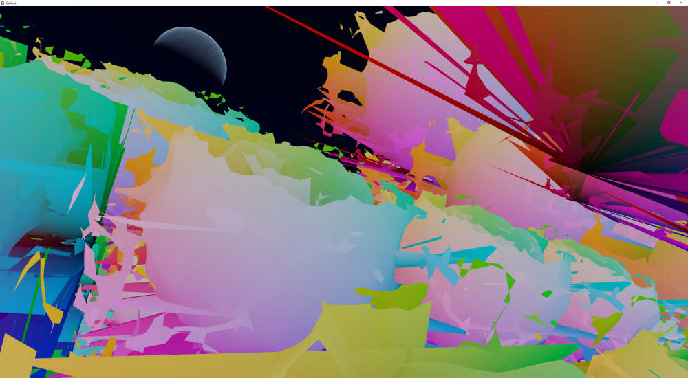
But anyways, I’ll finish off with pictures of some spectacular disasters that have occurred during this development process. It’s all art, right? 🙂
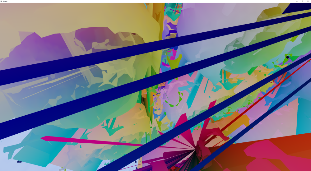

Amazing!
LikeLike
Im a middle school student ,i like it!
LikeLike
Hey, Do you use an octree in your dual contouring implementation?
Also, I’m trying to implement it right now, but I seem to have the same triangle problems as you had on the pictures, Thanks!
LikeLike