I had a realisation that the functionality of my voxel level-of-detail blending technique might not have really been documented anywhere. Others have probably already implemented the same idea (this technique may even already have a name, please tell me if you know), but it’s something I didn’t read about anywhere – I went googling for things like “smooth voxel LOD blending” etc, and didn’t come up with much technical info on how any sort of smooth voxel LOD transitions could be done, except for in a ray casting approach found here, which doesn’t really apply. So I just went with my instincts and came up with something that worked surprisingly well. The end result looks much like what Miguel did, presumably for the first time in Voxel Farm. Although as far as I know he hasn’t really elaborated on exactly how it works.
So here’s an article about how I’ve done it for my voxel asteroids! The implementation’s still not quite complete (some small gaps appearing occasionally, and the odd “pop”), but it’s good enough for this explanation. I plan to use this technique on my planet terrain as well once it’s finished. For info about how I’m extracting the voxel surface on the GPU in the first place, see my previous article on voxels.
Firstly, see the first half of the above video to get a feel for the vertex movements that occur during blending between detail levels (you may have to watch in fullscreen HD to be able to see the edges clearly). If you are familiar with adaptive tessellation you may be seeing some familiar patterns. To someone who hasn’t seen a wireframe rendering of adaptive tessellation before, this is often what it looks like – edges in the mesh looking like they split into two, sideways.
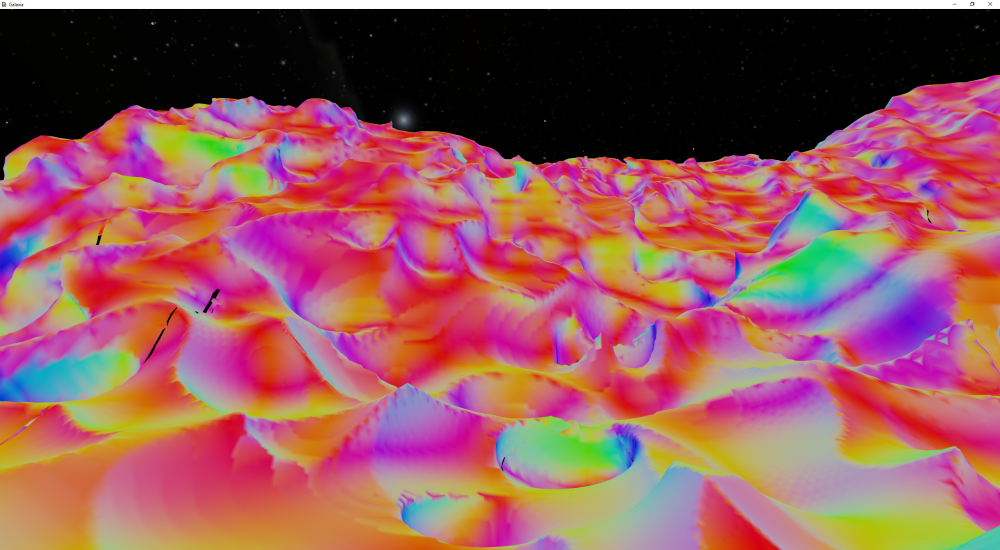
The edge splitting effect is noticeable in these images as well:
So, what’s really going on here? The simple answer is that the vertex positions and normals are blended with the vertex at the equivalent location in the parent node, such that at the exact point that a node splits, the new child node vertices are completely blended into the parent position, giving the visual appearance that the node hasn’t split at all. Much like how the LOD blending works for my planet terrain, as the new child nodes get closer to the camera their vertices “morph” back to their original positions (and normals). It’s a straightforward idea, but as always in graphics development, quite a few complexities appear during the implementation. So for the long answer, keep reading.
To start with, the main advancement from my previous voxels post is the LOD implementation itself, which is octree based. The octree nodes are culled against the viewing frustum, and split with the standard 1/d technique, which in my implementation looks more like:
ApparentSize = NodeSize / NodeDistance
SplitValue = ApparentSize - NodeRenderingDetail
if ( SplitValue >= 0.0 ) { /* split this node (recurse) */ }
else { /* queue this node for rendering */ }
Where NodeSize is the radius of the node in the world space, NodeDistance is the node’s center distance from the camera, and NodeRenderingDetail is an adjustable setting. Which is all fairly standard, except maybe for the SplitValue, which is the value that will end up being used to calculate the LOD blending factors. ApparentSize and SplitValue are stored in the node object for later use. At this point, some probing of the voxel density function is also done on the CPU prior to rendering to discard nodes that are far away from the surface. Then once the list of nodes to render is obtained, they are sorted from near to far to reduce overdraw.
The relevant node data (each node representing a chunk of voxels) is packed in the sorted order into a graphics resource (i.e. a buffer), which will result in the order that the chunks are finally rendered.
A couple of changes were required to the update phase described in my previous post on voxels. The voxel data generated in step 1 needed to be enlarged to support a wider range of sampling outside the current chunk. To also accommodate doing an ambient occlusion sampling, a few extra data points were added to bring the size to 39x39x39. Since 39 nicely divides by 3, the compute shader is run in thread groups of size 39x3x1 (117 total threads each). Therefore N x 13 x 39 thread groups need to be dispatched (where N is the number of chunks being updated).
The other main change in the update phase was added to step 10, where the cached vertex data is updated. To accommodate the LOD blending, each vertex no longer needs just its own position and normal, but also those of the parent cell’s vertex. Essentially this means just performing the same set of calculations twice for the vertex, but with different samplings of the voxel data.
The current cell’s position within the voxel data in step 10 is a 3-component uint, which is the primary input into the shader obtained from the group and group thread IDs, which will cover the range [0,0,0] to [32,32,32], representing the 33x33x33 vertices that make up a 32x32x32 cell chunk. So this means that we can simply determine the parent cell’s coordinates by subtracting the modulus of 2 (excerpt from step 10 compute shader) :
[numthreads(33, 11, 1)] //need to run (N,3,33) groups, where N is the chunk count.
void main(uint3 gtid : SV_GroupThreadID, uint3 gid : SV_GroupID)
{
   uint3 v = uint3(gtid.x, gid.y*11 + gtid.y, gid.z); //the current cell data indices
   uint3 bv = v + 4; //the chunk edges are inset by 4 in the input data (39x39x39)
   ... (this cell's position and normal calc's using bv)
   uint3 pv = bv - (v % 2); //the computed parent cell data indices
   ... (parent cell's position and normal calc's using pv)
   ... (finally, output the calculated data into the vertex cache)
}
Obviously when doing the sampling for the parent cell, the data points to sample will need to increment by 2 instead of 1 since the parent data is represented by every second sample from the child data.

So on to the rendering phase, where the “magic” happens here.
Before the rendering phase begins, the correct LOD blending factors for each node need to be calculated. The SplitValue previously calculated for each node is used as the LOD blending factor for that node’s child nodes. This is because at the exact point that a node splits, its SplitValue will be equal to zero. The SplitValue will also increase as the child nodes get closer to splitting, thereby being the ideal basis for those child blending factors. The only problem with using SplitValue directly is that it tends not to increase fast enough, and it can go above 1 (which should be the maximum value of a blending factor). So as a shortcut the blending factor is calculated by multiplying by a constant (saturate() just clamps the value to 0..1 range as in HLSL) :
BlendFactor = saturate(ParentNode.SplitValue * 10.0f)
Ideally the blend factor would be based on not only the parent node’s SplitValue, but the child’s as well, ranging from 0 when the parent just split, to 1 when the child node is about to split. This would result in a more constant blending over the full LOD range, and may be done in a future upgrade. If anyone knows a simple method of doing so, please let me know! (I think the maths should be fairly straightforward, I just haven’t put any time into it)
The node center camera relative positions and the blending factors are packed along with the other node information in the sorted node info buffer for use by the render shaders (primarily the geometry shader).
So now in the geometry shader, for each vertex being output the corresponding parent position and normal values are available as well as the vertex’s original position and normal. Finally, the chunk’s LOD blend factor is then used to simply blend the parent values with the original values, resulting in the smooth LOD transitions.
But there’s still a major problem! At the join between two adjacent chunks, the vertices will only line up perfectly if both chunks are at the same LOD and have exactly the same blend factors. This means that there will be unsightly gaps appearing along all the joins that need to be filled. Luckily, the LOD blending scheme provides an elegant solution to this issue.
Much like in my planetary terrain implementation, node adjacency information is calculated before rendering. This is done by first adding all the nodes to be rendered into an STL map (C++ equivalent of C# Dictionary<T>), keyed by the node’s center position (note: integer position vector – may not work for floats!). Then a second pass tests for the visibility of all the sibling nodes by calculating the sibling positions from the node’s position and size, and checking if they exist in the map. If a sibling was found, the sibling’s LOD blend factor is written into an edge blending array for the node (otherwise 0.0). This array is also included in the node info buffer to be accessed by the shaders.
Now in the geometry shader, when processing an edge vertex, the appropriate blending factor is selected out of the edge blending array. If the node’s own blending factor is smaller than the value obtained from the array, the node’s own blending factor is used instead. This ensures siblings sharing an edge will both use the same blend factor along that edge. And finally, if the matching edge sibling is split, a value of 1 is used. (This is how I currently have it implemented, but I realise while writing this that these extra checks could be done on the CPU beforehand and the appropriate values written into the edge blending array. I will definitely fix that because it will improve performance).
And that’s it! There shouldn’t be any gaps appearing any more. The only exceptions are now corner cases (i.e. diagonally adjacent nodes), which do appear but are quite infrequent. To account for this, the edge blending array described above will have to be expanded to include the corners. But I think it’s OK for now, at least until the occasional small gap really annoys me.
There’s also an issue when a cell is determined to contain the isosurface but the parent cell doesn’t. This may occur if the surface passes through one face of the parent node, but none of the edges. In this case, the vertices end up blending into an appropriate parent position, but then when the LOD switches to the parent, that vertex doesn’t exist, resulting in a visible “pop” when the faces attached to that vertex suddenly disappear. I have a couple of ideas to solve this problem, but I haven’t had a chance to play around with it yet. The solution will probably involve blending with a sibling of the parent, rather than the parent itself.
Well, that turned into a lot more than I was planning to write… 1800 words!! Hopefully it all makes sense because I wrote it over a period of a few days. I’ll finish off with a few images obtained during the process of implementing all this. Have fun!


This LOD transition and generation of voxels is one of the smoothest ever.
It’s almost imberceptible.
LikeLike
Very interesting approach. I have been working on a DC rendering engine for some time aswell and refused to do chunk stitching. I managed to mask chunk borders with using overlaps, that obviously is less than ideal though. Looking forward on implementing your geomorphing approach.
Here is my work for reference… https://www.youtube.com/watch?v=HTPyrcmyyCM
LikeLike
Geomorphing is the word you are looking for! Very cool work btw.
LikeLike
Indeed, it is a form of geomorphing but I was more referring to this specific technique with voxels. My heightmap terrain also uses geomorphing but in a much different way.
LikeLike
On a different note, have you looked into using manifold dual contouring? Someone called Lin has a good implementation of it and i was concidreing trying it myself. ( it could greatly improve mesh quality )
Also, i was wondering why you didn’t take advantage of DC mesh simplification capabilities.
LikeLike
I’ll have to spend some more time to research manifold DC, thanks for mentioning it! Nonmanifold vertices are a problem in this implementation, maybe that can help me find a solution. 🙂
Regarding simplification – it’s a trade-off between doing the extra processing to simplify the mesh in an LOD-friendly manner, and just drawing the extra triangles. It also might be problematic to implement wholly on the GPU, I haven’t tried. Perhaps it’s something I’ll investigate more in the future. But keep in mind that I have taken the approach I did because I like to try and keep everything as simple as possible, and obviously adding simplification actually would add a lot of complexity (as silly as that may sound in English, heh)
LikeLike
Not sure as for how much complexity it would add since generally the logic should already be pretty much there ( more or less). As for LOD friendly simplification, i ensure i do not simplify chunk borders which makes it still match up nicely. ( It MAY be slightly visible although i have not found that to be an issue as you can see in my video. )
I am sure you are aware of the blog by nglidea and his GPU implementation of DC, though i am not 100% sure right now if he does does with simplification, might be worth a look.
LikeLike